
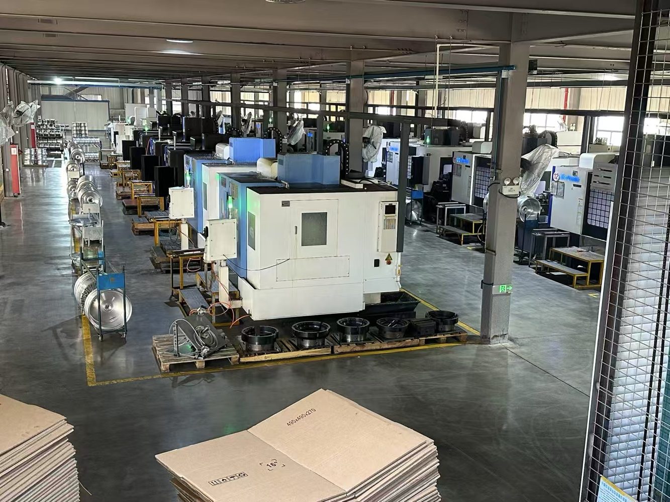
From Aluminum Billet to Finished Alloy Wheel
Alloy wheel manufacturing is a controlled production process, not only a styling exercise. For customers who buy custom forged wheels, the important question is how the supplier controls material consistency, wheel strength, fitment accuracy, surface durability and export protection from the first aluminum billet to the finished shipment.
In a professional production system, each stage leaves evidence: material batch records, forming parameters, heat-treatment control, CNC machining data, dimensional inspection, runout and balance checks, finish inspection and packaging records. This is what allows a wheel order to be repeated accurately, especially when different sizes, offsets, PCDs and finishes are produced for multiple vehicle applications.
| Production stage | What is controlled | Why customers should care |
|---|---|---|
| Aluminum billet selection | Alloy grade, billet diameter, batch traceability, visible surface defects | Stable raw material reduces variation before forging and machining |
| Forging / forming | Preheating, die condition, pressure, deformation ratio and grain flow | Improves density and helps reduce porosity compared with many casting routes |
| T6 heat treatment | Solution treatment, quenching, artificial aging and hardness stability | Supports strength, toughness and dimensional stability after machining |
| CNC machining | PCD, center bore, offset, mounting pad, bolt seat and brake clearance | Turns the forged blank into a wheel that fits the target vehicle correctly |
| Final inspection | Runout, balance, coating condition, label and packing verification | Reduces vibration, finish damage and mixed-order risk before export |
Material Control: Why the Billet Matters
The quality of a forged alloy wheel begins before the wheel has a shape. The aluminum billet must match the intended material specification and must be traceable by batch. For forged wheel production, buyers should ask whether the supplier controls alloy documentation, billet surface defects, storage condition and preheating consistency. A good surface finish cannot compensate for unstable raw material.
Many forged wheel applications use heat-treatable aluminum alloy systems because they provide a useful balance of low weight, corrosion resistance, machinability and mechanical strength. The Aluminum Association describes 6xxx series alloys as heat-treatable aluminum alloys with silicon and magnesium as key alloying elements; this explains why material selection and temper control are so important in wheel manufacturing.
Forging: Creating a Dense Wheel Blank
Forging compresses heated aluminum into a stronger and denser blank. The process changes the internal grain structure and can reduce internal porosity when compared with lower-cost casting methods. For customers, the important point is not simply whether a wheel is called forged, but whether the supplier can explain how the blank is formed, how consistency is controlled and how later machining preserves the intended strength.
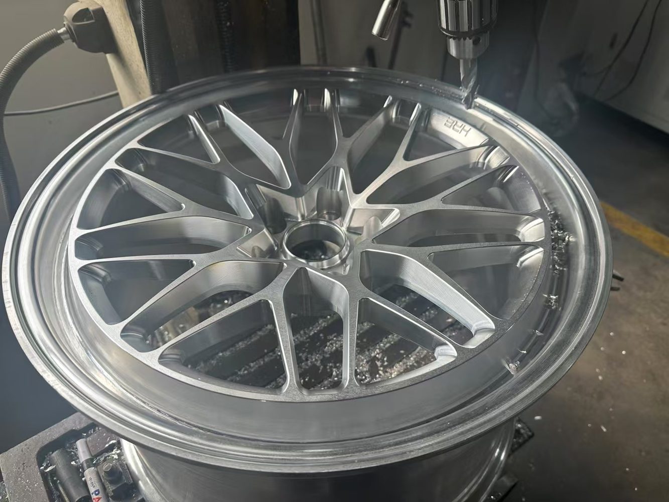
Heat Treatment and CNC Machining
After forming, the blank normally goes through heat treatment to stabilize mechanical properties. CNC machining then defines the final wheel geometry: center bore, PCD, offset, mounting pad flatness, bolt seat geometry, brake clearance, spoke profile and decorative machining details. This is where a strong blank becomes a vehicle-specific product.
Fitment errors are often expensive because they appear only when the wheel is installed on the vehicle. That is why PCD, CB, ET, brake clearance and runout should be treated as engineering data, not only catalog information. A supplier should be able to confirm these values before production and inspect them before finishing.
| Inspection item | Typical production check | Customer value |
|---|---|---|
| PCD and bolt seat | Coordinate inspection, fixture gauge or calibrated measuring method | Protects safe installation and correct bolt alignment |
| Center bore | Diameter check and hub-centric fitment verification | Helps reduce vibration caused by poor wheel centering |
| Offset / ET | Mounting face position relative to wheel centerline | Controls brake, suspension and fender clearance |
| Radial and lateral runout | Rotational measurement after machining and finishing where required | Supports smoother rotation and fewer customer complaints |
| Surface and coating | Visual standard, coating coverage, clear coat and packing audit | Improves appearance consistency and export durability |
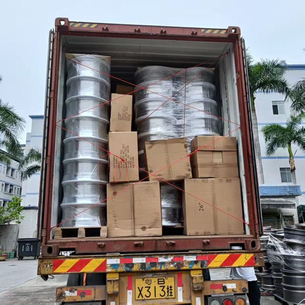
What Customers Should Look For
When evaluating an alloy wheel supplier, customers should look beyond product photos. A reliable production partner can explain the whole route: billet selection, forging method, heat treatment, CNC machining, finish control, inspection records and export packaging. The stronger the process visibility, the easier it is for customers to repeat the same wheel quality across future orders.
What makes the process an engineering chain?
An alloy wheel is a safety-critical rotating component, so its manufacturing route cannot be judged by the final surface alone. The process links alloy chemistry, billet soundness, deformation, heat treatment, machining datums, rim geometry and fatigue performance. A change made early in the route can appear much later as a machining defect, a runout problem or an unexpected fatigue result.
The research paper Manufacturing Processes of Car Alloy Wheels describes the usual routes as casting, machining and forging, and explains why finite-element analysis and process simulation are useful before production changes are released. Its practical point is important for buyers: the correct wheel is not simply the lightest wheel. It must achieve the required stiffness, load rating, brake clearance and dimensional repeatability at an acceptable mass.
| Production stage | Engineering variable | What the buyer should verify |
|---|---|---|
| Material and billet | Alloy grade, melt quality, batch identity and surface condition | Can the supplier trace the billet to the work order? |
| Forming | Die fill, grain flow, rim profile and local wall thickness | Is the forming route defined for the wheel size and load requirement? |
| Thermal cycle | Solution treatment, quench and artificial ageing | Are temperature records linked to the production batch? |
| Machining and inspection | Datums, PCD, CB, ET, runout and balance | Are inspection results available before shipment? |
How forming and heat treatment change wheel performance
Forging applies compressive deformation to a heated billet and can produce a denser, more directionally controlled structure than a conventional casting route. The benefit is not an automatic guarantee of strength; die filling, deformation distribution and subsequent thermal treatment must be controlled together. Local underfill, excessive flash, sharp section changes or an unsuitable machining allowance can still create weak process points.
The supplied spinning-forming study gives a useful example of parameter sensitivity. For an A356.2 aluminium billet, it examined a staged temperature window: approximately 420 °C during initial heating, 400 °C in pre-deformation, 380 °C in the main deformation zone and 370 °C during finishing. The study also reported a contact-temperature fluctuation target within about +/-5 °C. These values are study conditions, not a universal recipe; the correct window depends on alloy state, tooling, section thickness and equipment.
Heat treatment then stabilizes the mechanical condition of the formed material. Solution treatment, rapid quenching and artificial ageing affect precipitation, hardness and dimensional stability. In production, the useful control is the complete record: furnace temperature uniformity, transfer time, quench condition, ageing cycle and the disposition of any batch outside the approved window.
Why CNC machining is more than cosmetic cutting
After forming and heat treatment, CNC machining converts the blank into a vehicle-specific interface. A stable datum scheme is used to control the center bore, mounting pad, bolt-hole pitch circle, valve hole and spoke geometry. The center bore locates the wheel on the hub; PCD is the diameter of the bolt-hole pattern; ET or offset describes the mounting-face position relative to the wheel centerline. These dimensions determine fitment and brake clearance, not just appearance.
Inspection should separate radial runout, lateral runout and dynamic imbalance. Runout is geometric deviation during rotation, while balance concerns the distribution of mass. A wheel can pass one check and fail another. This is why a professional control plan records the measurement method, datum, gauge resolution, fixture condition and acceptance limit instead of reporting only “passed”.
| Check | Typical method | Failure risk if uncontrolled |
|---|---|---|
| Center bore and PCD | CMM, calibrated gauges or vision-assisted measurement | Hub fitment, bolt seating or installation problem |
| Radial and lateral runout | Rotational dial or electronic runout measurement | Vibration, tire seating or steering complaint |
| Mass balance | Dynamic balancing machine | Excessive balance weights or high-speed vibration |
| Fatigue performance | Cornering and radial fatigue testing as specified | Crack initiation under cyclic wheel loading |
How a buyer can evaluate a wheel manufacturer
Ask for the process route, alloy designation, fitment drawing, load rating, inspection scope and sample approval method. For a custom program, also ask how design revisions are controlled, how CNC programs are released, how mixed sizes are separated and how nonconforming wheels are quarantined. A supplier that can connect the drawing, batch number, machine record, inspection report and carton label is demonstrating process control rather than relying on a catalogue photograph.
A process map buyers can use during a factory review
A useful manufacturing review follows the wheel through linked control points rather than judging a finished sample in isolation. Ask where the alloy identity is recorded, how the blank is formed, which heat-treatment condition is approved, how the CNC datums are established, and how the final wheel is released. The value of this sequence is that it connects engineering intent with evidence that can be checked on the production floor.
For a custom program, the drawing, process sheet and inspection record should use the same language for diameter, width, PCD, center bore, ET, load rating and finish. When these records agree, a buyer can compare samples, pilot lots and repeat orders with much less ambiguity. When they do not, an attractive prototype may conceal a fitment or repeatability risk.
| Evidence area | Control detail | Customer value |
|---|---|---|
| Material | Alloy identity, heat number and incoming check | Establishes a traceable starting point |
| Forming | Forging or spinning route and process window | Controls section distribution and grain flow |
| Machining | Datums, PCD, CB, ET and mounting pad | Protects vehicle fitment |
| Release | Runout, balance, finish and shipment records | Creates objective evidence before dispatch |
References
The technical discussion above is informed by the two supplied research papers and the following public standards and technical sources. Parameter ranges cited from the supplied spinning-forming study are reported study conditions, not universal production limits.