
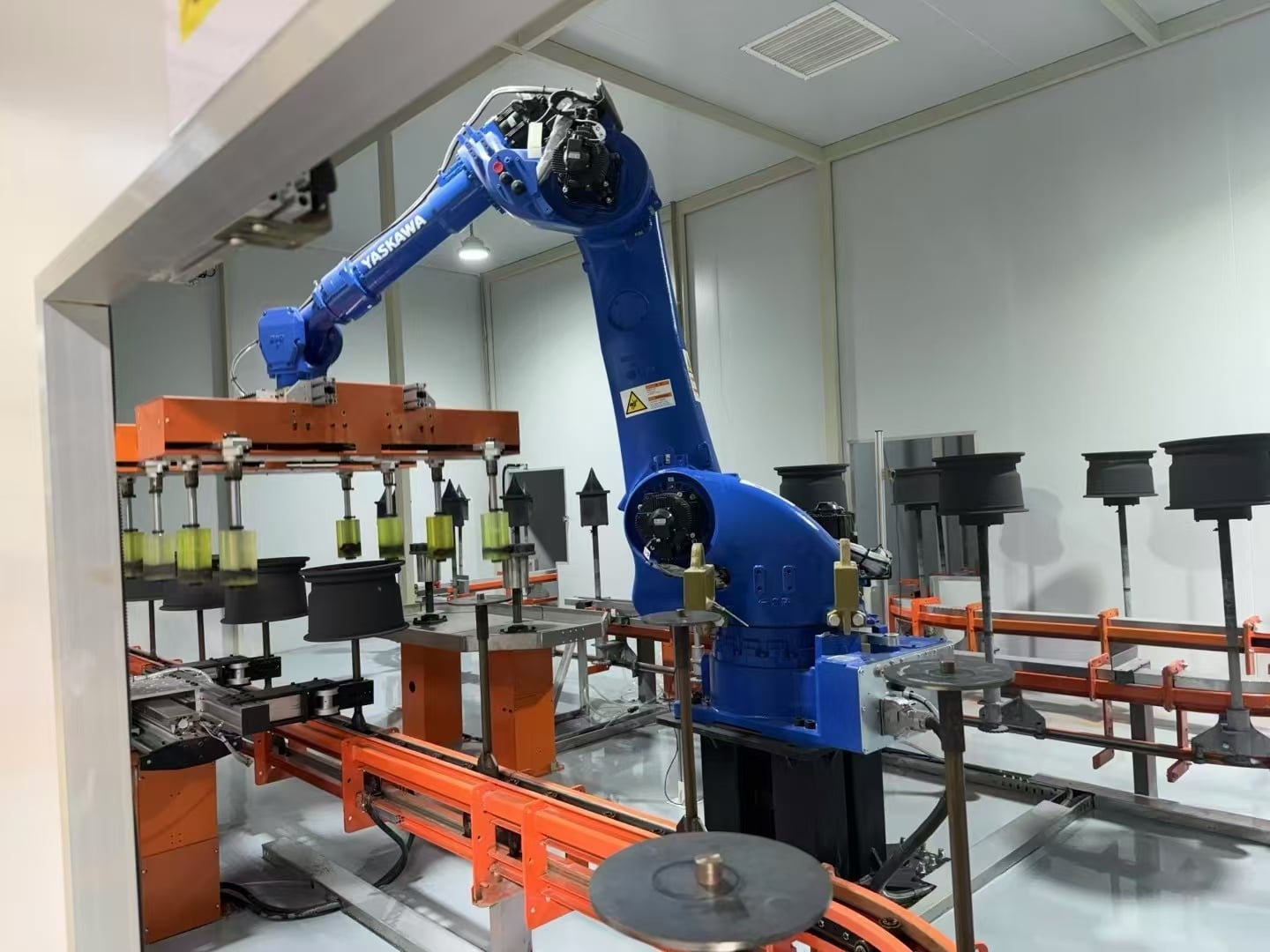
Why CNC Machining Determines Wheel Fitment
Forging gives a wheel blank its material foundation, but CNC machining gives the wheel its final fitment. For customers ordering custom forged wheels, machining is the stage that controls whether the product can be installed safely, rotates smoothly and clears the vehicle brake system.
Key dimensions such as PCD, center bore, offset, mounting pad flatness, bolt seat geometry and brake clearance must be machined and inspected as a connected system. If one value is wrong, the wheel may still look attractive but create vibration, installation difficulty, caliper interference or uneven clamp load.
| Machined feature | Function | Risk if inaccurate |
|---|---|---|
| PCD | Positions the bolt holes on the pitch circle | Incorrect bolt alignment and installation stress |
| Center bore | Locates the wheel on the vehicle hub | Poor centering, vibration or hub-fit problem |
| Offset / ET | Controls the mounting face position relative to wheel centerline | Brake, fender or suspension interference |
| Mounting pad | Provides the contact surface against the hub | Clamp-load instability and runout risk |
| Brake clearance | Provides space for calipers and related hardware | Physical interference after installation |
From Forged Blank to Vehicle-Specific Wheel
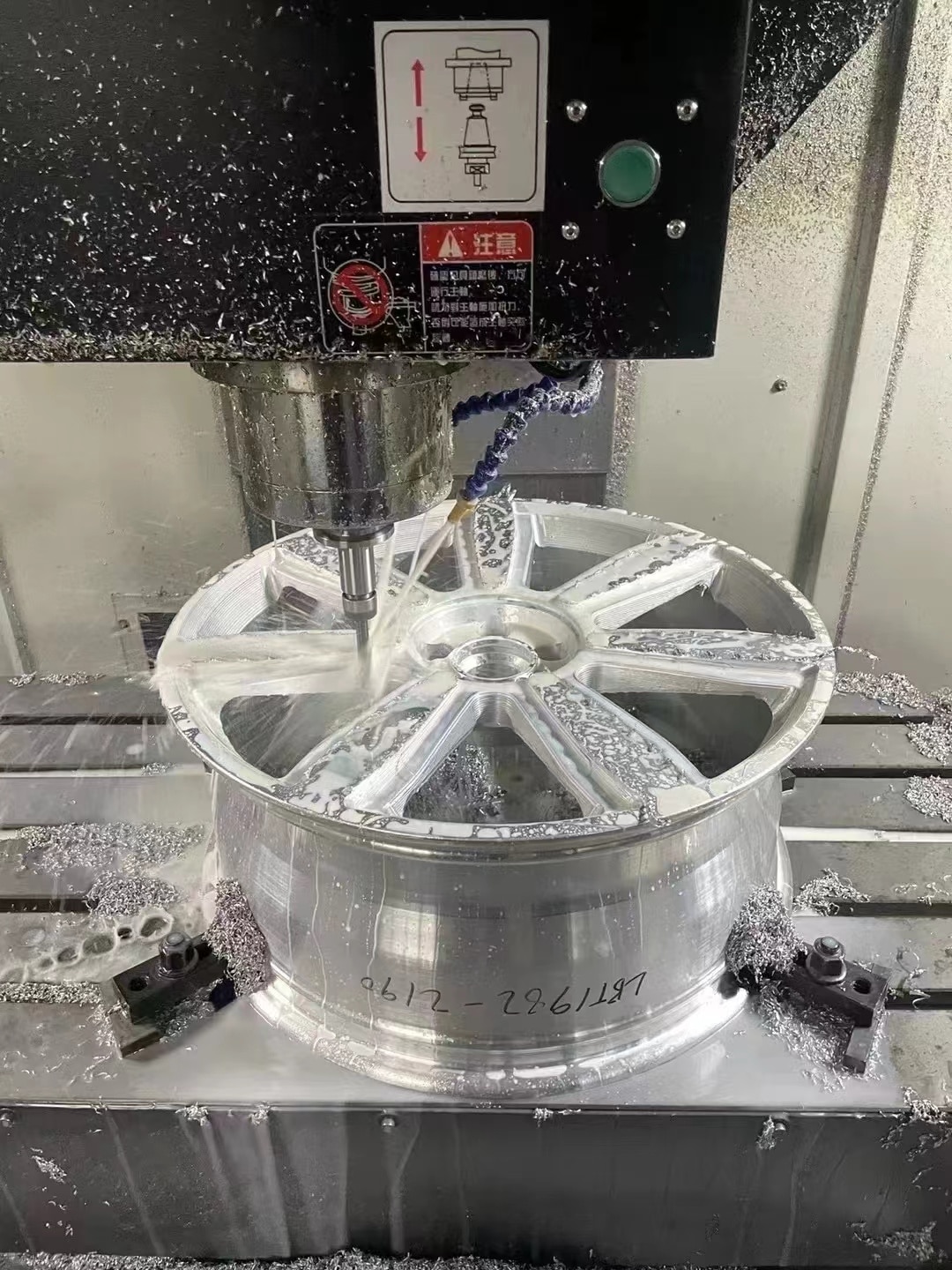
The CNC route begins with datums. Operators establish reference surfaces, clamp the blank and then machine the face, barrel, mounting pad and bolt pattern in a controlled sequence. Fixture stability matters because a small clamping error can become visible as runout, mounting pad variation or offset deviation.
For custom orders, machining data should be connected to the target vehicle application. A wheel designed for a large SUV, a performance sedan or an off-road build may require different load rating, brake clearance, concavity, width and offset. The production team must translate the design into repeatable machine coordinates and inspection checkpoints.
Machining Controls Customers Should Ask About
Customers do not need to know every internal machine parameter, but they should understand what is being controlled. Useful questions include: How is the wheel centered in the fixture? How is PCD verified? How is brake clearance confirmed? How are radial and lateral runout checked? How are revision changes controlled for repeat orders?
| Process checkpoint | Inspection method | Customer benefit |
|---|---|---|
| Datum setup | Reference surface and fixture check | Maintains repeatability across batches |
| PCD / bolt seat | Coordinate measurement, gauge or controlled fixture | Protects installation accuracy |
| Center bore | Diameter gauge and hub-fit check | Supports hub-centric fitment |
| Offset | Mounting face position measurement | Controls stance and component clearance |
| Runout | Radial and lateral runout measurement | Reduces vibration complaint risk |
Why Runout and Balance Matter
Runout describes how much a rotating wheel deviates from its intended circular path. Radial runout relates to up-and-down variation, while lateral runout relates to side-to-side variation. Dynamic balance addresses mass distribution. These checks support smoother rotation and help reduce customer complaints after installation.
Customer Takeaway
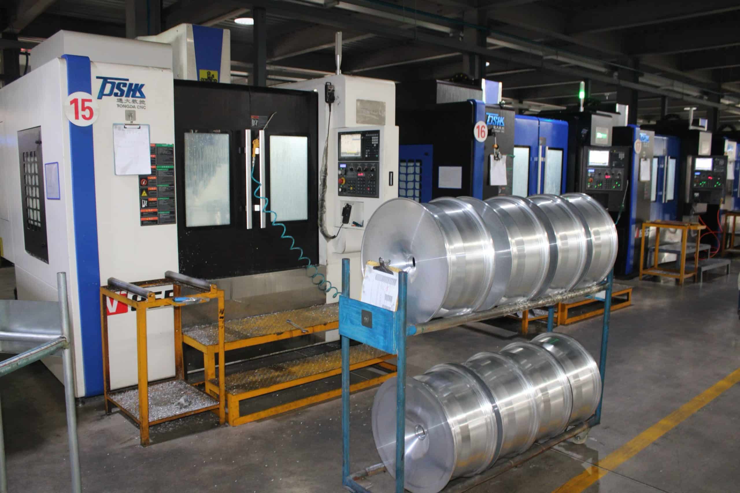
CNC machining is where forged strength becomes practical fitment. A capable alloy wheel supplier should be able to discuss PCD, CB, ET, brake clearance, mounting pad flatness, runout and balance with the same confidence as wheel style and finish.
Why machining accuracy controls wheel fitment
CNC machining is the transition from a heat-treated forging or spun blank to a vehicle-specific wheel. It establishes the interfaces that connect the wheel to the hub, fasteners, brake assembly and tire. The process therefore has two simultaneous objectives: remove material efficiently and preserve a controlled relationship between every functional datum.
The supplied spinning-forming study describes rough turning on the inside and outside surfaces before CNC finishing, with roughly 0.5-1.0 mm left as machining allowance for locating and finishing. It reports position tolerances around +/-0.05 mm for the mounting face, valve hole and bolt-hole pattern in its test route, and assembly runout at or below 0.1 mm. These are study values and must be confirmed against the approved drawing, machine capability and applicable market requirement.
| Datum or feature | Definition | Why the control matters |
|---|---|---|
| Center bore (CB) | Diameter locating the wheel on the vehicle hub | Controls concentric location and installation fit |
| PCD | Pitch circle diameter of the bolt-hole pattern | Controls fastener alignment and interchangeability |
| ET / offset | Mounting-face position relative to wheel centerline | Influences track width, brake clearance and suspension space |
| Mounting pad | Machined face contacting the hub | Controls seating flatness and axial location |
| Bead seat and rim profile | Tire seating geometry | Supports inflation retention and tire installation |
Datum strategy, fixturing and tool-path stability
A repeatable CNC route begins with a repeatable datum. The fixture must support the blank without distorting a thin rim section, while the locating surfaces must be clean and protected from chips. If a worn locator or incorrect clamping force changes the position of the blank, the machine may produce dimensions that are internally consistent but shifted from the vehicle reference system.
Tool paths should be sequenced so that high-load roughing does not damage the surfaces later used for precision location. Cutting direction, tool overhang, spindle condition, coolant delivery and tool wear all influence burr formation and surface finish. On thin rim sections, excessive radial engagement can increase deflection and leave a profile that meets a local gauge but fails a full-section scan.
Process capability is stronger when the manufacturer monitors the characteristic during production rather than waiting for final rejection. The research reviewed by the review cites DMAIC, process capability indices and control charts as ways to move machining control from detection toward prevention. In practice, that means trending CB, PCD, mounting-pad runout and tool-life behavior by machine, shift and batch.
Inspection should measure the complete rotating interface
A CMM or calibrated optical system can verify coordinate relationships, but a wheel should also be checked in rotation. Radial runout is the variation in the radial direction as the wheel turns; lateral runout is axial wobble. Dynamic balance measures mass distribution and cannot be substituted by a dimensional check. The inspection fixture must reproduce the wheel’s intended mounting condition, otherwise the result may reflect fixture error rather than wheel error.
| Control layer | Record to retain | Customer value |
|---|---|---|
| First-piece approval | Drawing revision, program revision and dimensional report | Confirms the production route matches the approved sample |
| In-process control | Tool offset, wear limit, coolant and fixture check | Prevents drift across a production run |
| Final dimensional check | CB, PCD, ET, pad flatness and runout data | Supports fitment decisions and complaint investigation |
| Traceability | Wheel mark, batch, machine and inspector | Links a shipped wheel back to its process history |
Questions for a CNC wheel supplier
Request the fitment drawing before quoting, including diameter, width, PCD, CB, ET, brake-clearance envelope and load rating. Ask which dimensions are measured 100 percent and which are sampled, what the gauge resolution is, and how the supplier reacts when a trend approaches the limit. These details reveal whether CNC machining is being managed as a controlled engineering process.
References
The technical discussion above is informed by the two supplied research papers and the following public standards and technical sources. Parameter ranges cited from the supplied spinning-forming study are reported study conditions, not universal production limits.