
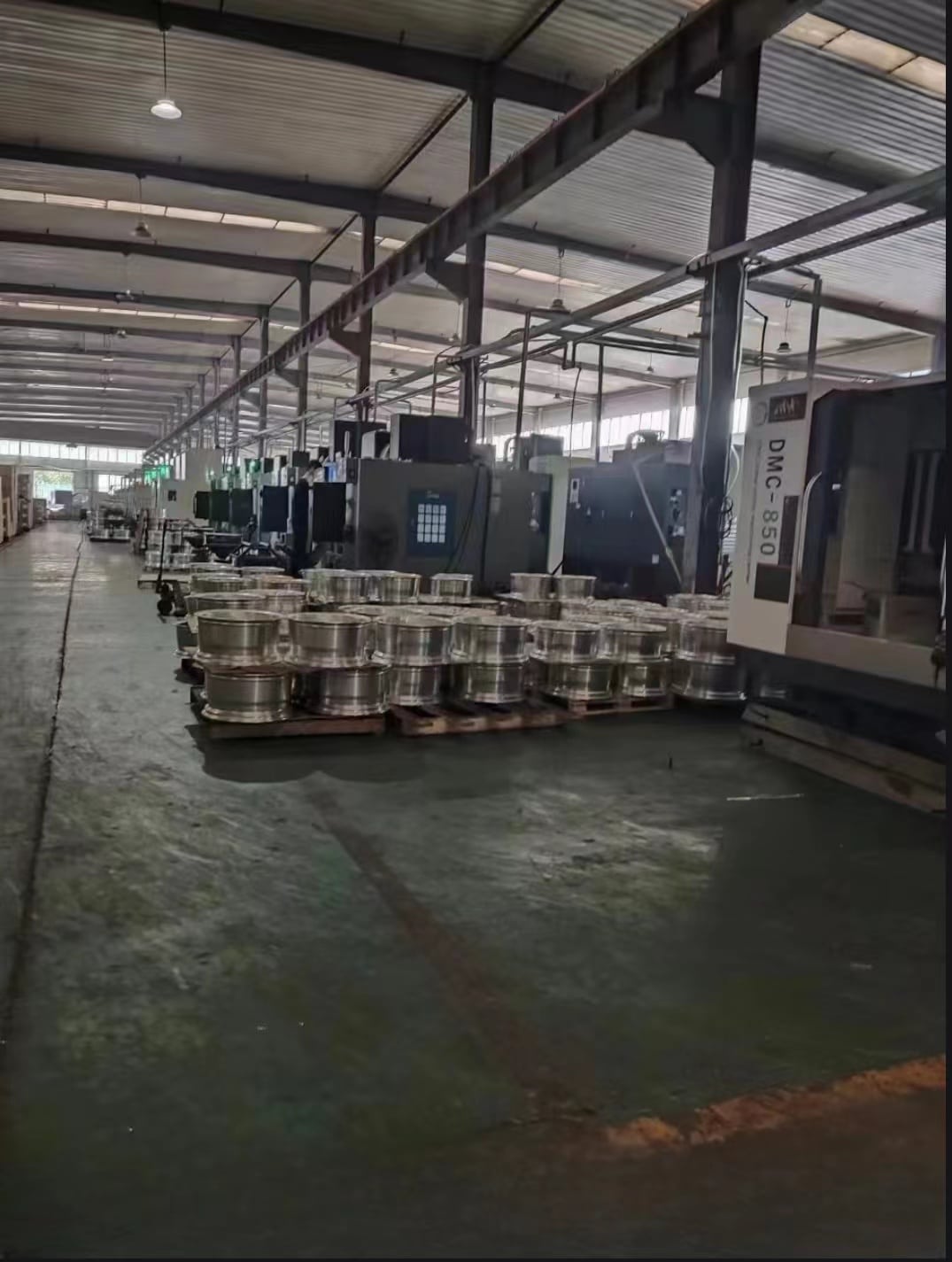
What forging actually gives the wheel
Closed-die forging is not only a shape-making step. It is a structural step that pushes the metal into the geometry of the wheel while encouraging grain flow to follow the load path of the finished part. That is one reason forged wheels are valued in demanding applications: the process is designed to support the structure, not just the appearance.
The wheel blank must therefore do three things at once. It must fill the die cavity correctly, leave the right machining allowance and preserve enough symmetry so that the next operation can control the final dimensions. If one of those goals is missed, the batch may still look impressive on the shelf but behave poorly during machining or service.
A spinning-forming optimization study makes the same point from a different route: temperature, feed movement and blank symmetry influence wall distribution and dimensional stability. In forging, that means the die and the billet have to be managed as a system. Small changes in blank balance or heat can create large changes in the final blank envelope.
The route from heated billet to controlled blank
The closed-die stage usually begins with a heated billet that must be transferred quickly enough to preserve its intended temperature window but carefully enough to avoid distortion. The transfer timing, the preform shape and the die closure all work together. If the billet cools too much, the fill may be incomplete. If it enters too hot or too soft, the blank may flash excessively or lose symmetry.
That balance is why a forging department should not work as a standalone press room. It should work as part of a route that includes heating, handling, preforming, final forming, trimming and inspection. Each step changes the next. Buyers who understand this route are usually better able to separate a controlled forging process from a factory that is only pushing metal through a die.
The quality of the grain flow also matters for real-world wheel use. A wheel experiences cyclic loading, cornering forces and repeated stress around the spoke and hub regions. Closed-die forging aims to organize the metal so the load path is more favorable than a simple cast shape. That is one reason forged wheels often justify their position in the performance market.
| Forging variable | What is controlled | Why buyers should care |
|---|---|---|
| Die fill | Pressure, temperature and material flow | Prevents underfill and missing geometry |
| Grain flow | Direction of deformation through the blank | Supports strength along spokes and rim |
| Flash | Excess material and trimming quality | Affects cleanliness and later machining time |
| Machining allowance | Remaining stock after forging | Keeps the final wheel within tolerance |
Why blank symmetry matters before machining
A blank can be accepted visually and still be unsuitable if the material is heavier on one side than the other. That asymmetry changes how the blank sits in the fixture, how the tools engage the surface and how much stock remains after each cut. A stable blank allows the CNC program to do what it was designed to do instead of compensating for hidden variation.
This is why good forging control includes more than press force. The factory should think about preform shape, heating profile, dwell time, die wear and trimming quality. Those details decide whether the blank will enter the machining cell with stable geometry or with a problem that will reappear later as runout, balance variation or poor offset consistency.
If the wheel design uses thin spokes, deep pockets or aggressive face geometry, this becomes even more important. The forming route has to leave enough allowance to support the final surfaces while still keeping the wheel as light and efficient as the specification allows. The best forged blank is the one that gives the machining room without carrying unnecessary metal.
How die wear changes the result
Die wear is one of the more subtle risks in forged wheel production. A worn die may not look dramatic, but it can slowly change the way material fills the cavity and how the flash forms around the edge. Over time, that means the same press settings can produce slightly different blank outlines. If the supplier does not monitor die condition, the change can show up downstream as extra machining stock or inconsistent spoke mass.
A disciplined factory therefore tracks press history, die inspection and trimming quality together. It is not enough to say the wheel is forged. The supplier should be able to explain how often the die is checked, how wear is measured, and how the team decides whether a blank should be reworked, released or held for tool maintenance.
Typical forging defects and what they signal
| Symptom | Likely cause | Effect on later operations |
|---|---|---|
| Underfill | Low temperature or weak flow route | Missing detail or reduced rim geometry |
| Fold or lap | Improper metal movement in the die | Weak surface area that may appear later |
| Excess flash | Poor die balance or oversized preform | Extra trimming work and higher scrap risk |
| Blank warp | Cooling imbalance or uneven release | Fixture difficulty and machining drift |
How to read the forging route in a professional factory
A supplier with mature forging control can explain the route in clear steps: billet heating, transfer timing, preform deformation, final cavity fill, flash trimming and blank inspection. If the factory can show what it measures at each point, the buyer can judge whether the process is designed or merely improvised.
The inspection record should also show that the blank still leaves enough machining allowance for the downstream geometry. That means the forging team and the machining team need a shared understanding of the design, because a blank that is too near the final shape may save material but will often create more risk later.
From a customer perspective, the main question is simple: does the forged blank behave like a controlled product or like a rough shape? Grain flow, die fill and symmetry are the evidence. If those are stable, the wheel has a much better chance of finishing within tolerance and arriving without hidden structural compromise.
Practical buyer questions
- How is the billet heated and transferred so the blank stays in the right temperature window?
- How does the supplier confirm die fill without excess flash or underfill?
- What inspection proves the blank remains symmetric before machining?
- How is machining allowance set for the final wheel program?
- How are die wear and press history linked to the batch record?
Buyer checklist
- Ask how the factory controls heating temperature before forging.
- Check whether preforms and die routes are used for difficult geometries.
- Confirm that blank symmetry and trimming are inspected before machining.
- Request information on machining allowance and blank release criteria.
- Review whether forging records stay linked to the order batch.