
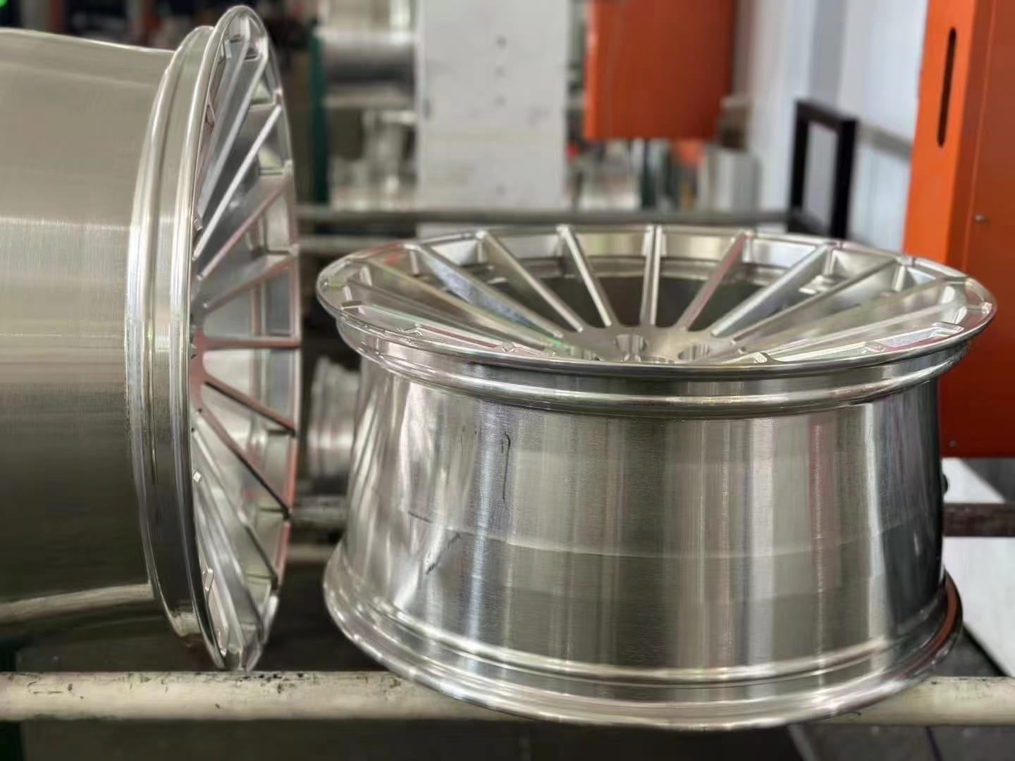
Why machining is the step that decides fitment
Forging creates the blank, but CNC machining creates the vehicle-specific wheel. The tool path sets the center bore, PCD, offset, mounting pad and the surfaces that determine whether the wheel will mount properly on the target hub. That is why machining is not a cosmetic step; it is the fitment step.
PCD is the pitch circle diameter of the bolt holes. The center bore is the hub-location diameter. Offset, often written as ET, describes where the mounting face sits relative to the wheel centerline. These values work together, so a supplier that treats them as isolated numbers is already at risk of making a part that looks correct but does not install correctly.
A practical CNC process also has to manage runout, clamp stability and the condition of the datum surface. If the blank is located differently from part to part, the same program can produce different real-world results. The machine may be accurate on paper, but the wheel will only be accurate if the fixture, the datum and the inspection system are stable together.
How machining transforms a blank into a vehicle part
Machining is the stage where the wheel becomes specific to the vehicle. The blank may already have the right mass and general shape, but the CNC program gives it the exact center bore, bolt-circle geometry, offset and face accuracy that the target hub requires. This is where the wheel stops being a generic forged part and becomes a fitment-controlled component.
Because of that, the machining cell has to care about more than numbers in a drawing. It has to care about how the blank is seated, how the spindle runs, how the tools enter and exit the cut, and how chips are cleared. Even a tiny change in fixture position can create a real difference in the finished wheel. That is why datum discipline is just as important as tool quality.
The best way to think about CNC wheel machining is as a chain of controlled decisions. The blank is located. The datum is confirmed. The rough surfaces are removed. The precision surfaces are finished. The final dimensions are measured against the target fitment. When each step is linked, the wheel becomes repeatable. When any one step is weak, the wheel becomes a risk item rather than a finished product.
| Dimension | What is controlled | Customer value |
|---|---|---|
| PCD | Bolt-hole circle and spacing | Protects wheel-to-hub alignment |
| Center bore | Hub location diameter | Helps the wheel center correctly on the vehicle |
| Offset / ET | Mounting face position | Supports brake and suspension clearance |
| Mounting pad | Flatness and face condition | Improves secure seating on the hub |
| Runout | Radial and lateral deviation | Reduces vibration and steering shake |
A stable datum is the foundation of repeatability
The datum is what lets the machine know where the part really is. If the wheel blank is seated slightly differently each time, the program may still run, but the results will drift. That is why high-quality machining starts with a fixture that protects the blank from distortion while keeping the center relationship consistent.
Once the blank is fixed correctly, the machining route usually follows a logical sequence: rough cutting, finish cutting, hole-circle work, surface cleanup and final measurement. The factory should know which surfaces are used as the reference, where tool wear is expected to affect dimensions and how often the first-piece is checked before batch release.
For custom alloy wheels, the most important thing is that the machining team and the sales spec speak the same language. Width, center bore, offset, brake clearance and target vehicle should never be treated as unrelated fields. When they are reviewed together, the final wheel becomes much easier to trust.
Typical machining risks and how they appear
The most common machining problems are not dramatic failures. They are small drifts that slowly move the wheel away from the drawing. A tool that is gradually wearing may change the finish quality before it changes the dimension. A fixture that is slightly loose may increase runout before anyone notices. A surface that is not properly cleaned before clamping may create location error that later appears as offset variation.
This is why the best factories do not wait for a complaint to appear. They collect first-piece data, watch tool life, track the condition of the datum and verify the same wheel points again during batch release. When the process is managed that way, the customer can trust that the wheel was not only machined correctly once, but can be machined correctly again.
Inspection points that reveal real machining control
| Inspection point | Method | Why it matters |
|---|---|---|
| First-piece approval | Measure before the batch continues | Proves the setup and tool path are correct |
| PCD / center bore | Gauge, CMM or dedicated measurement | Confirms wheel-to-hub compatibility |
| Offset / face position | Check the mounting pad against the drawing | Protects vehicle clearance |
| Runout | Rotational measurement around the wheel axis | Reduces vibration and imbalance complaints |
Why tool wear and clamp stability matter
A fast CNC program is not automatically a stable one. Tool wear, chip loading and clamp pressure all affect the result. If a cutting edge dulls, the face finish and the dimensional consistency can both drift. If the clamp is too aggressive, the wheel can deform slightly during machining and recover after release, which means the measured part and the installed part may not match.
The best factories therefore link inspection to process control. They do not measure only at the end. They monitor the setup at the start, the first part in the middle and the batch at release. That is how they keep the wheel within the drawing rather than merely inside a rough visual acceptance range.
A well-run machining line also knows where it is vulnerable. Deep spokes, thin lips and sharp transitions often demand more attention than flat surfaces. If the supplier can explain those weak points clearly, the buyer usually has a better understanding of why the process is valuable and where the risk would otherwise appear.
Practical buyer questions
- What datum surface is used for wheel location during machining?
- How often are first-piece checks performed during the batch?
- What happens if runout moves outside the accepted window?
- How is tool wear tracked before it starts affecting the finish?
- Which dimensions are matched to the target vehicle before release?
Buyer checklist
- Ask how the fixture controls the datum and prevents part distortion.
- Confirm that PCD, center bore and offset are all inspected, not just one dimension.
- Request the first-piece report and the batch release criteria.
- Check how the factory watches runout before final approval.
- Verify that the machining route is linked to the specific wheel order.